
COATINGS FOR NONLINEAR OPTICS

Image Source Credit: LIDARIS
Coatings change surfaces
Thin-film vacuum-deposited coatings can change the reflectivity of an optical surface. Often, the goal is to minimize a surface’s reflectivity at one or more wavelengths of light so that less light is wasted. Another benefit of reducing unnecessary reflections is to avoid harmful “stray beam” reflections. In some cases, coatings can act as a barrier to protect the substrate from the environment, making the optic less susceptible to chemical or photochemical attack involving contaminants such as water or hydrocarbons. For example, water degrades the nonlinear material barium borate (BBO), and some coatings can help protect BBO.

Figure 1. LBO crystals that have optical coatings on their input surface.
This article will concentrate on coatings applied by vacuum deposition, which gives durable reliable coatings. There are other techniques for reducing surface reflectivity such as sol-gel coatings or nano-structured surfaces. These two other techniques have, or may have, applicability to nonlinear optics. In general, their advantage is that they can be highly resistant to optical damage. Their disadvantage is that they are mechanically fragile and not readily cleaned.
Nonlinear crystals change the color (equivalently, the wavelength) of light
Nonlinear optical crystals are a special class of materials that can convert laser light from an efficiently generated wavelength to a more useful wavelength. For example, crystals of lithium triborate (LBO) convert 1064 nm light from a Nd:YAG laser into 532 nm or 355 nm light, which is more effectively absorbed in materials processing applications. LBO, BBO, KTP, KDP (Potassium Dihydrogen Phosphate), KD*P (Potassium Dideuterium Phosphate), and LiNbO3 (Lithium Niobate) are examples of crystals used for nonlinear conversion.
Coatings help thwart reflections from stealing light
Reflective losses from a polished crystal depend on the refractive index of the crystal, which in turn depends on the light’s wavelength and polarization relative to the crystal. At near-normal incidence, these reflective losses range from about 4% for low index crystals, like KDP, to about 15% for high index crystals, like LiNbO3. Reflective losses of this magnitude are significant, and the losses generally get worse if there are two uncoated surfaces per crystal and potentially more than one uncoated crystal. Anti-reflection (AR) coatings can reduce the losses. AR coatings can be comprised of a single layer or many layers (forming a coating stack), where back reflections from each layer collectively cancel each other, reducing the net reflection. Each coating layer is typically just a fraction of a wavelength of light thick. Often the reflectivity of an AR coating stack is less than 1.0% per surface. Less than 0.1% or much lower is possible.

Using a coating stack with more than a single layer, and with potentially a more complex design, the reflectivity at one or more wavelengths can be engineered to be significantly lower. (See Fig. 3)
However, coatings are costly and have their own issues.
Getting what is needed from coatings
Issues coatings may have include:
1. The coatings themselves are often more susceptible than the underlying substrate to laser induced damage, even if the coatings are less susceptible to chemical or photo-chemically induced damage. (see Fig. 4 & 5 below)
2. The coatings can suffer delimitation or cracking, especially during thermal cycling. (see Fig. 6, 7, and 8)
3. Coatings usually increase the amount of absorption and scatter from a surface.

Figure 4. Nanosecond laser-induced damage on the dielectric coating measured in the vacuum environment. (Photo used with permission from LIDARIS LIDT Service.)

Figure 5. Femtosecond laser-induced damage on the dielectric coating. (Photo used with permission from LIDARIS LIDT Service)
Specifying what you want your coatings to do
A list of important specifications is shown below. Note that many of these specifications affect whether the coatings will be damaged by laser irradiation.
· What wavelength, or wavelengths, of light will be used?
· How low do you want the reflectivity to be per surface?
· Will you ever need to clean the surfaces after they are coated?
· What is the operating and non-operating environment for the optics—the temperature ranges and the atmosphere surrounding the optics?
· What is the angle of incidence/exit of the light at the crystal, and what is the polarization of the light?
· Will the light be continuous (CW) or pulsed? If it will be pulsed, what is the pulse width and pulse repetition rate?
· How powerful are your laser beams, and what is the shape and diameter of the beams?
· What is your required laser induced damage threshold (LIDT) at the relevant wavelength(s) and pulsewidth(s)? This is a specification that can be calculated or measured, and it is in units of energy (Joules) or power (Watts) per square centimeter. Your specified LIDT must exceed the energy or power of your laser beam divided by the beam area at your coating.
· How large are your nonlinear optics?
· How long must the coating survive in operation (measured in time or number of pulses at a specified repetition rate)?
When you have a draft of your specifications, it is a good time to bring in an expert on coatings or to contact several reputable coating suppliers about what they offer. They can design a coating along with choosing the coating materials and the coating process.
At GAMDAN Optics, we work with various coating professionals to design and implement your application’s unique coating requirements. GAMDAN’s innovative team has helped many laser scientists and designers over the years develop and qualify tooling and recipes to fit their needs. Contact us today to discuss your system’s qualifications.

Figure 2. Adding a simple single-layer quarter-wave (λ/4) dielectric coating to a substrate can reduce the net reflectivity for light going into the substrate. In this illustration, light is shown reflecting from the air-to-coating interface and from the coating-to-substrate interface. Together these two reflections come close to cancelling each other because the round-trip distance through the coating is half the wavelength of the light, and consequently these two waves are out of phase.
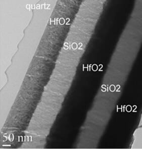
Figure 3. A multi-layer coating consisting of a stack of HfO2 and SiO2 layers shown as an end-view with SEM imaging. Filipescu, M., A. Palla-Papavlu, A. Bercea, L. Rusen, M. O. Cernaianu, V. Ion, A. Calugar, L. C. Nistor, and M. Dinescu. "Antireflective coatings with high damage threshold prepared by laser ablation." Applied Physics A 125 (2019): 1-12.

Figure 6.

Figure 7.
Fig. 6 & 7 are real examples of crazed coatings. Why this happens is a differing expansion (or other mismatches) between the film and the underlying substrate which puts the film under stress and can lead to this type of failure. It can also lead to solitary cracks as seen here.

Figure 8. A crazed / cracked coating. In this case it is paint, not a thin film dielectric, but this image presents a better understanding of the concept of why this happens, which is the same with a thin film or a thick film. (Photo Credit Source)
DR. WILLIAM GROSSMAN, AUTHOR
Will Grossman is a consultant retained by GAMDAN Optics, Inc., and his role is to help our customers be more successful with nonlinear optics. His technical expertise includes laser design, nonlinear optics, and laser reliability. Dr. Grossman’s laser designs are used around the world in commercial products. More on the author can be found here.
Did you enjoy this article? Sign up to receive articles we publish straight to your email box here: